Bending forces and stress
Internal force in beams
When we consider the internal forces of a beam, we take a cross section and consider the forces acting on it. The internal forces are:
- Shear force is the force acting parallel to the cross-section.
- Bending moment is the moment generated by the variation of forces acting perpendicularly to the cross-section.
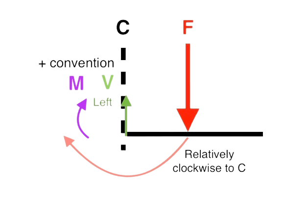
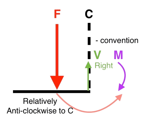
The idea is that if the acting force is relatively clockwise to the cross-section , it is positive. The following is the signs of internal forces for a positive moment:
- V: (L R )
- M: (sagging moment is positive)
When considering couple moments, their effect is independent of the point of application, but they have no effect if they are not in the cut of the beam during analysis. They do not exert any force on the beam, but will affect the reaction forces at supports.
To find the internal forces at cross-section where no loads apply, we consider the left and right side of the section:
- V: on either side
- M: on either side about
Note that the sums are all signed by convention. (e.g. A force is positive if it points upwards on the left side.)
This also gives us the fact that and , signed by convention on both sides.
To find the interal forces at the left and right cross-section at a point where loads or moments apply:
- Left side:
- Right side:
Diagramming internal forces
The two internal force diagrams are and diagrams. gives the shear force at distance from the left side of the beam.
The following is the relation between the internal forces:
Where is the distributed load acting on the beam.
- This tells us that the slope of the diagram at an interval is the value of at that interval.
- This tells us that the slope of the diagram at an interval is the value of at that interval.
Steps to follow
- Solve for reaction forces
- Draw the FBD of a cut from the leftmost side to a location with distance from the leftmost force not analysed
- Analyse the FBD of the cut (solve for and )
- Draw the graphs in the cuts and repeat for all cuts
Figurative steps:
To analyse a distributed load , consider the FBD of the whole system on the left, then let be the distance from the leftmost force analysed:
\large
Signing conventions
By convention, we consider the positive convention with respect to the cross-section. That means, if the force is clockwise to the cross-section, it is positive..
Bending stress
The neutral axis always passes through the centroid of the beam. It is netural as the length remains unchanged for the surface that the axis passes through.
The distance from the netural axis is denoted (positive downwards).
The bending stress is given by:
Where is the bending moment, is the distance from the neutral axis (centroid), and is the moment of inertia of the section.
The formula also tells us that the bending stress is proportional to the distance from the neutral axis, and the neutral axis experiences no stress.
Related: Moment of inertia